Introduction
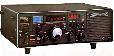
The Yaesu FRG 7000
is a colorful, vintage receiver that is still fun to use. The main drawback
when used in AM mode is the availability of only one IF bandwidth, that is way
too wide (9kHz at –6dB, measured) in crowded band conditions (What ? “Crowded
bands” in 2017 ?). The narrow filter (2.8 kHz at – 6dB) is accessible only in
USB/LSB modes.
However, this
limitation can be overcome with a very simple modification, that is absolutely
not-invasive and completely reversible. With this modification when you select
the AM mode the receiver uses the Wide Filter, while when you select the AM-ANL
mode the receiver uses the Narrow Filter.
But first let me
state it very clearly: do it at your own risk. I will accept no liability for any
damage you will do to your radio, to yourself or to this sector of the Universe
by following the procedure outlined in this document.
The mod
Since the filters
are selected electronically by activating a diode, the modification is very
simple: just “cut” a connection on the “mode” switch and rewire it. This will
allow you to select the Narrow Filter in AM-ANL mode, while the standard AM
mode uses the Wide Filter.
The mode switch is
easily accessible from underneath the radio, there is no need to dismount
anything apart removing the receiver’s cover; the photo below shows the
position of the mode switch (circled in red).
In the schematic
below the modification is shown: just “cut” a connection (red cross) on S2(e)
switch and rewire it with the blue wire. The section (e) of switch S2 select
the desired IF filter (CF01 –wide- or
CF02 –narrow-) by grounding a diode (and hence activating it).
As standard, CF01
is selected for AM and AM-ANL modes, and CF02 for USB and LSB modes. By
rewiring section (e), we activate CF01 only for AM, and CF02 for
USB/LSB/AM-ANL; as simple as that !
Please note that I kept the ANL circuit operative, since I could hardly notice its effect; if you want, you can disable it but then the modification will be more invasive and you will need to rewire also section (a) of S2.
On the left the
band switch before the mod. The connection that need to be interrupted is the
one circled in blue, easily accessible, where the white-and-blue wire is
connected.
There is no need to
dismount the switch.
The two pins of the
switch are soldered together; I cut the wire and then used a de-soldering pump
to remove the solder and separate them.
On the right the
band switch after the mod. Note the added green wire that jumpers the fourth
(and last) pin of the switch (AM-ANL position) to the first and second pins
(USB/LSB position), i.e. to the white-and-brown wire.
The white-and-blue
wire is now connected only to the third pin (AM position).


